Wetting tension
VIBAC uses the method ASTM D 2578
This method uses standard wetting tension solutions of varying ratio of formamide in cellosolve to create different surface tensions (36- 56 dyne/cm).
A test solution is selected with a rating that is less than the expected film value. Using a new cotton-tipped applicator, the solution is applied on the film. If the applied solution hold together for more than 2 s, rather than breaking up into droplets, then the test is repeated with next higher tension solution. If the solution holds together for less than 2 s, the test is repeated with a lower surface tension solution.
This scenario is reiterated until you can determine the solution that comes nearest to wetting the film surface for exactly 2 s. This is the film’s wetting tension.
The values are expressed in dyne/cm (or in mN/m).
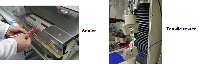
Tensile strength and elongation at break, elastic modulus
 VIBAC uses the method ASTM D 882
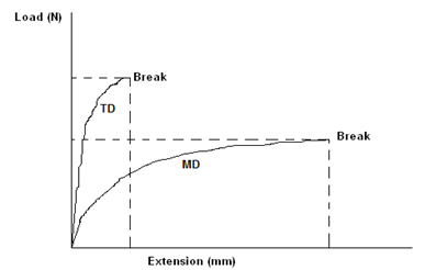
Tensile testers measure a film’s resistance to being pulled apart at a constant rate of speed. VIBAC Film uses this test to report three significant properties.
Tensile strength at break: it is the force, measured at the break of the film, divided by the film’s initial cross-sectional area. Values are expressed in N/mm2.
Elongation at break: it is the percent change in length of the material under stress from start to break. The units are %.
Elastic modulus: it is a stress-strain ratio, calculated from any point on the initial straight line portion of the load-extension curve. It is measured just as the material begins to experience tension. This value is an indicator of the film’s stiffness and resistance to elongation in use.
The unit is N/mm2.
Machine direction (MD) and transverse direction (TD) values are evaluated and reported separately for all these parameters.
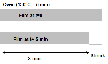
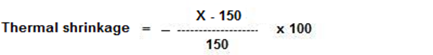
Thermal shrinkage
VIBAC uses the internal method OPMA TC4a
Thermal shrinkage is the change in length of a film sample subjected to a specific elevated temperature. VIBAC tipically measures this property at 130 °C. Machine direction (MD) and transverse direction (TD) values are evaluated and reported separately. Units are reported as % change from the original dimension.
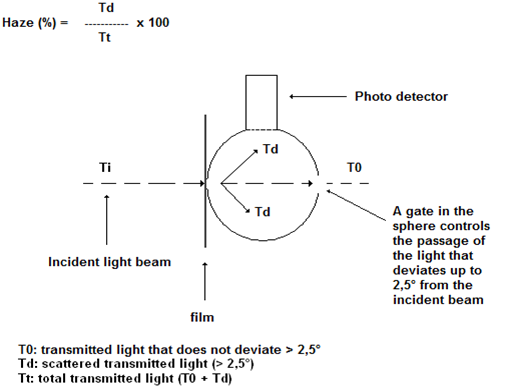
Haze
VIBAC uses the method ASTM D 1003
Haze is the scattering of light by a film that results in a cloudy appearance or poorer clarity of objects when viewed through the film. More technically, haze is the percentage of light transmitted through a film that is deflected more than 2,5° from the direction of the incoming beam.
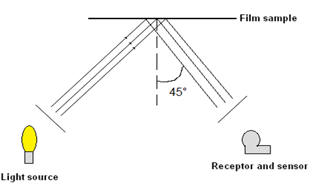
Gloss
VIBAC uses the method ASTM D 2457
Gloss is a measurement of the relative luster of a film surface. VIBAC uses 45-degree gloss, where the incident light beam strikes the film surface at a 45-degree perpendicular angle. A sensor measures the amount of light reflected by the film at a mirror image angle. The gloss value is the ratio of this reflected light to incident light.
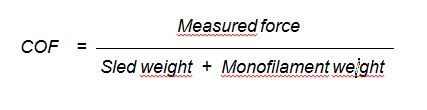
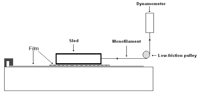
COF
VIBAC uses the method ASTM D 1894- DIN EN ISO 8295-04
Coefficient of friction (COF) is a unit less number that represents the resistance to sliding of two surfaces in contact with each other. Generally this value is between 0 and 1. The values are measured after constant motion is achieved (dynamic COF).
Seal strength and seal range
VIBAC uses the internal method OPMA TC4b
Seals, which are produced in controlled conditions of jaw design, temperature, pressure and dwell, are measured in terms of force required to open the seam. The following properties are calculated and reported.
Seal strength: it is the maximum force to peel open a seal made at specified conditions. Unit is g/cm.
Seal strength: it is the value obtained at 130°C.
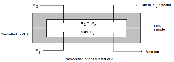
Oxygen transmission rate (OTR)
VIBAC uses the method ASTM D 3985
VIBAC uses Mocon OX-TRAN instruments for measuring OTR. The instrument design is consistent with the ASTM D 3985 standard.
Dry nitrogen gas is swept through a chamber, where the test film acts as the membrane separating this stream from an oxygen stream on the other side. The partial pressure difference creates a driving force for oxygen molecules to diffuse through the film to the low-pressure side. The film barrier determines the rate of oxygen permeation.
The test is complete when the equilibrium is achieved; that is, it is complete when the sensor detects a constant amount of oxygen in the nitrogen carrier stream.
This rate is the sample OTR and is recorded in units of cm3 (O2)/m2/24h at 23 °C and 0% r.h.
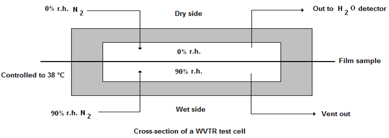
Water vapor transmission rate (WVTR)
VIBAC uses the method ASTM F 1249
VIBAC uses Mocon PERMATRAN W instruments for measuring WVTR. The instrument design is consistent with ASTM F 1249.
Dry nitrogen gas is swept through a chamber where the test film acts as the membrane separating this dry gas stream from a “wet” nitrogen stream on the other side. The partial pressure difference creates a driving force for the water vapor to permeate through the film to the low-pressure side.
The barrier of the film determines how much water vapor can transfer, and this is continuously measured by an infrared detector in the outgoing stream of the other side.
The test is complete when the equilibrium is achieved, which is when the infrared sensor detects water molecules leaving the dry chamber at a constant rate. This rate is the sample WVTR and is recorded in units of g (H2O)/m2/24h at 38 °C and 90% r.h.
Optical density (specific for metallized film)
VIBAC uses the internal method IOQ 824.18
A unidirectional light beam is directed onto the film sample. The light that is transmitted through the film is measured.
VIBAC uses Macbeth densitometers to measure the optical density.
The optical density value represents the following calculation and relationship to % light transmission.
Optical density (unitless) = log10 (Li/Lt) = log10 (100/light transmision (%))
Table below compares optical density values to light transmission values.
| Optical density |
2,0 |
2,1 |
2,2 |
2,3 |
2,4 |
2,5 |
3,0 |
| Light transmission (%) |
1,0 |
0,8 |
0,6 |
0,5 |
0,4 |
0,3 |
0,1 |
Metal adhesion (specific for metallized film)
A sample of the metallized film is placed on a smooth and flat surface with the metallized layer facing up. Approximately 150 mm length of adhesive tape is applied to the surface and is smoothened with a thumb to ensure good contact. The sample of the film is held down with one hand and the tape is peeled back at 180° with other hand in one smooth movement. The test substrate for metal removal and the used tape for metal transfer are examined using a strong backlight.
Release properties (Cling level)
VIBAC uses the internal method IOQ 824.100
The properties are related to the film's capacity to release cold adhesives, spread on another “supporting” film.
The active side of the film (release layer) of is laid down on the untreated side of the “supporting” film, previously spreaded with cold seal. After sample conditioning (pressing weight of 20 tons for 24 h -effective pressure ~124 kg/cm²), the force necessary to separate the films is recorded.
Antifog properties
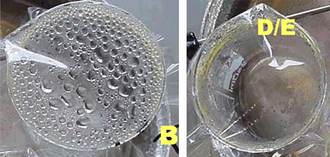
Antifog agents are used in polymeric film to ensure that any condensation of water occurs as a uniform, invisible, layer of water rather than as a series of individual droplets that are aesthetically undesirable.
The Antifog Test
Fill a 250 ml beaker with 200 ml of water and cover the top of it with a sample of the test film. Place the beaker in a temperature –controlled cabinet at 4°C. Observe the appearance of the film, according to the ratings A to E described in the below table for a total period of 1 week.
| Description |
Performance |
Rating |
| An opaque layer of small fog droplets |
Very poor |
A |
| An opaque or transparent layer of large droplets |
Poor |
B |
| A complete layer of large transparent drops |
Poor |
C |
| Randomly scattered or large transparent drops |
Good |
D |
| A transparent film displaying no visible water |
Excellent |
E |